
Development of an Automated Double Ring Infiltrometer
Author / Reference
- Maheshwari, B. L., 1996:
Development of an Automated Double Ring Infiltrometer. -
Australian Journal of Soil Research, Vol. 34, p. 709-714.
VL reprint under:
VL Irrigation & Hydrology - vl_ref_id_x_0025
Abstract
A double ring infiltrometer is often used for measuring infiltration characteristics in the field, but the measurements using this are time consuming and tedious, especially when several tests are to be monitored at a site. This is because the infiltrometer in its present form requires continuous attention and therefore limits the number of tests that can be monitored at a site in a given time. An automated double ring infiltrometer has been developed to overcome these limitations. It consists of inner and outer rings, water level sensors, water container, depth sensor, solenoid valves, 12 volt car battery, laptop computer and software to perform recording and basic analysis of the infiltration data. The infiltrometer requires little attention once the test is started and the computer provides up-to-the-minute summary of infiltration results while the test is still in progress. The automated infiltrometer worked very satisfactorily during the field trials and has considerable potential as a research and teaching tool.
Additional keywords
Infiltration measurement, soil-water movement.
Introduction
Ring infiltrometers are commonly used for in-situ measurement of infiltration characteristics. The infiltrometer can employ one or two concentric rings, and correspondingly it is called a single or double ring infiltrometer. The double ring infiltrometer is preferred because the outer ring helps in reducing the error that may result from lateral flow in the soil. Several researchers (e.g. Burgy and Luthin 1956; Bouwer 1963; Tricker 1978) have studied the effects of ring diameter and depth of water ponded in the rings on the reliability of infiltration measurement.
Why automate the ring infiltrometer?
In a ring infiltrometer test, a constant depth of water should be maintained in the rings and the volume of water infiltrated with time must be recorded during the test. This means continuous attention is required during the test and the measurement with the infiltrometer is time consuming and tedious, especially if it is to be done at several sites requiring replications. Due to considerable effort and time required in setting up the infiltrometer in the field, it is desirable to check trends and accuracy of infiltration characteristics being measured while the test is in progress. Then, if there is any problem in the measurement, some remedial action can be taken to obtain correct data.
To overcome the above difficulties and limitations, efforts have been made in the past with a limited success to automate the measurement. In particular, Constantz and Murphy (1987) developed a single ring infiltrometer with an automated Mariotte reservoir which enables automatic recording of flow from the reservoir but its use for a double ring infiltrometer still requires water level control in both inner and outer rings and the infiltrometer is far being automated. Ankeny et al. (1988) modified the set-up of Constantz and Murphy for use as a ’tension infiltrometer’ which is used for estimating sorptivity and unsaturated hydraulic conductivity and is very different from a conventional double ring infiltrometer. The set-up reported by Prieksat et al. (1992) is based on work of Constantz and Murphy (1987) and Ankeny et al. (1988) and uses pressure transducers for determining water flow out of Mariotte reservoir. The set-up is a kind of single ring infiltrometer with a small ring (102 mm diameter) and cannot be modified from its present design for use as a double ring infiltrometer.
The double ring infiltrometer of Matula and Dirksen (1989) requires 2 water containers, one each for inner and outer rings, and the water level in the inner ring is controlled through an arrangement of a float and photosensitive transistor but the elapsed time is recorded manually. This means, their set-up is only semi-automatic and the infiltration measurement cannot be automated fully.
In summary, no set-up has yet been reported that is capable of measuring infiltration without continuous attention during the test and at the same time provides up-to-the-minute summary of the infiltration data.
Automated ring infiltrometer
Recognising the limitations of a manual infiltrometer, a fully automatic set-up needs to be developed to enable (i) a precise control of water depths in the inner and outer rings, (ii) an automatic addition of a measured volume of water when required, and (iii) a summary of infiltration test results available at any time during the test. The summary may include the current and past information on the volumes of water added during re-fills, infiltration rates and cumulative infiltration depths with the elapsed time. Such a set-up is expected to make monitoring of tests less demanding and will provide a quick in-situ check on the progress of the data. The set-up will be particularly useful in a study that involves infiltration measurement at several sites requiring replications. Besides its use for research, an automated ring infiltrometer will also be an excellent teaching tool to show trends in infiltration characteristics and discuss some of the issues with the students while at the test site.
Materials and methods
Design of an automated ring infiltrometer
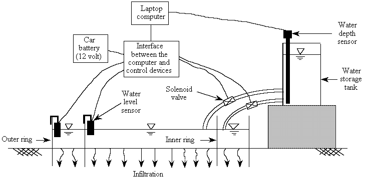
Figure 1:
Experimental arrangement in the field
[Source: Maheshwari, B. L., 1996]
While general details on ring infiltrometers are given in Bouwer (1986), Fig. 1 shows schematically an arrangement of different components of an automated double ring infiltrometer. The inner and outer cylindrical rings are inserted into the ground. Water is filled in these rings and infiltration occurs through the ground area enclosed by the rings. A constant depth of water level within each ring is maintained through an arrangement of water supply from a storage tank, solenoid valve and a water level sensor. When the water level in a ring drops below 5 mm from a pre-set value, the level sensor sends a signal to the computer which in turn instructs the solenoid valve to open and allows water from the tank to flow into the ring. The water flow stops when the level reaches the pre-set value in the ring, again through a signal from the level sensor (via the computer) to the solenoid valve. Between the inner and outer rings, the inner ring is given priority in re-filling of rings as this ring is more crucial for the infiltration measurement.
The volume of flow from the storage tank into the inner ring is calculated by measuring change in water depth in the storage tank with time when the solenoid supplying water to the inner ring is opened. The depth in the tank is measured by a depth sensor and transmitted to a laptop computer. The tank needs to be calibrated for the relationship between water depth and volume it occupies in the tank. The calibration needs to be done only once for a given tank. The data on volume of water added and elapsed time are continuously analysed and plotted on the screen, and thus provide current state of infiltration in the test. The main information displayed on the screen includes cumulative infiltration depth, current and average infiltration rate, time elapsed since beginning of test and last refill of inner ring and a plot of cumulative infiltration depth with elapsed time.
Details of infiltrometer components
Software
As a part of this development, user-friendly software was developed for smooth operation of the infiltrometer. The software is written in BASIC and is available from the author upon request. At the beginning of the test, the software enables convenient recording of identification details of the test, calibration of the storage tank, testing of solenoid valves to check whether they are operating properly and filling of the rings to a required depth. During the test, it helps in storage and analysis of data, updated display of test results and termination of test if desired. The software also keeps track of elapsed time since beginning of test and times when refills of the inner ring occur. Furthermore, when the water level in the tank drops too low, it will generate a beeping sound to alert that it is now time to refill the tank. At this time, by pressing an appropriate key in the computer, the next refill of the rings can be suspended to enable refilling of the tank. If there is no one around to refill the tank, the computer will automatically conclude the test and store all the data collected.
Cylindrical rings
The inner and outer rings having diameters 300 and 500 mm, respectively, and height 500 mm are used in the set up. The rings are constructed of 3-mm-thick galvanised iron sheet so that they do not deform when inserting them into the ground. The bottom of each ring has a bevelled edge to prevent soil disturbance while the top 50 mm is reinforced with a metal strip to withstand heavy force of hammering during insertion.
Water level sensors
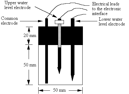
Figure 2:
Construction details of water level sensor
[Source: Maheshwari, B. L., 1996]
Two water level sensors, one each in the inner and outer rings, are used for maintaining appropriate depths of water in the rings. The level sensor consists of three electrodes, called common, upper water level and lower water level electrodes. The electrodes are housed in a 50-mm-diameter and 70-mm-long perspex tube ( see Fig. 2). One end of each electrode has an electrical lead that is connected to an electronic interface. In addition, the other end of the upper and lower water level electrodes have a pointed tip to precisely indicate the water level in the rings. The interface mentioned above is a control circuit between the laptop computer and the level sensors, depth sensors and solenoid valves, and its function is to process signals coming out of the sensors and solenoid valves and transmit them to the computer. The upper level electrode is vertically adjustable with the help of a thread provided on the top half of its length, whereas the lower level electrode is fixed in the perspex tube. This means the vertical clearance between the upper and lower electrodes can be changed easily, and the number of refills of the inner ring per unit time can be varied depending upon the infiltration characteristics of soil at the experimental site. Field tests showed that a clearance of 5 mm is generally satisfactory for the soils considered in the present study.
The sensor works on the principle of completing or not completing the electric circuit between the common and other two electrodes. The water between the electrodes acts as the conducting medium. As the water level in the ring drops due to infiltration, a break in the electric circuit between the common and the lower level electrodes occurs at some stage and sends a signal to the computer to start adding the water in the ring to raise the water level. On the other hand, as the water level rises due to the addition of water in the ring a stage is reached when the water level just touches the tip of the upper level electrode and completes the electric circuit between the common and the lower level electrodes; this sends a signal to the computer to stop adding further water in the ring. The cycle of completing and breaking of the circuits occurs through out the test and enables precise control of water levels in the rings. The water level in a ring will fluctuate vertically between the tips of the upper and lower level electrodes.
Other components
A cylindrical plastic container with a tap at the lower end is used for supplying water to the rings. The size of the container should be such that it requires no more than 1 or 2 refills to complete a test and allows easy transport to the field site. A container of 30 L capacity will generally be suitable for most field conditions except for those with high infiltration rates.
A commercially available depth sensor of capacitance type (Unidataª model 6521) was used for measuring water depth in the storage tank. The electronic interface designed was such that it enabled the depth sensor to detect very small drops (< 0.25 mm) of water levels in the tank. A detailed circuit diagram of the interface is available from the author upon request. The depth readings in the form of voltage from the sensor are transmitted to the computer for conversion into mm and storage for later analysis.
A large hammer (5 kg) and steel plate (1 m by 1 m by 5 mm) are used for driving the rings into the ground. A 12 V car battery is used as a power source for the solenoid valves, level sensors and depth sensor. A laptop computer with a printer port is used to control the solenoid valves, collect data from the depth sensor, note time at each re-fill and analyse infiltration data during the test.
Procedure for monitoring a test
The location for test on a given site should be such that it is typical of the site under consideration. This means test locations near fence lines, in gate ways, or areas that had abnormal surface disturbance are to be avoided. The rings are driven into the ground to a depth of 100 mm. It is very important that they are driven vertically so that there is minimal soil disturbance and that no gaps appear between the cylinder wall and the soil. To ensure that the rings are inserted vertically, the plate is placed on top of the rings and hammering is done in the middle and alternate edges of the ring.
The ground surface in the inner and outer rings is covered with a polyethylene sheet to prevent any infiltration before commencement of the test. By pressing an appropriate key in the computer, both solenoid valves can be tested to see whether they are operating satisfactorily. To avoid unnecessary refilling of the storage tank, the rings can be manually filled at the beginning to approximately the depth to be maintained (i.e. 100 mm) during the test. By pressing an appropriate key in the computer, it can be checked whether the rings have correct water level or not. If the depth is less than required, the computer can instruct the solenoid valves to allow flow of more water into the rings until the required depth is reached.
The test is commenced by removing the polyethylene sheet from the rings, thus allowing the water from the rings to infiltrate into the soil. At this point, an appropriate key of the computer is also pressed to hand the control of the test over to the computer. Afterwards, the set-up operates automatically with the solenoid valve automatically filling up the rings when the drop in water level in the rings due to infiltration exceeds a set value, that is 5 mm. At each re-fill of the inner ring, the depth sensor in the tank takes depth readings at the beginning and end of refill. These depth readings are recorded in the computer for analysis. Thus, the amount of water added along with elapsed time is automatically recorded.
During the test, all that needs to be done is to ensure that the water in the supply tank does not run out. When the rate of infiltration has reached a reasonable steady state, usually after 1 to 2 hours in most soils, the test can be concluded by pressing an appropriate key of the computer. This stops all operations of the infiltrometer and saves data collected during the test on a hard or floppy disc.
Results and discussion
Figure 3 shows results of one of the tests conducted during field testing of the infiltrometer. The set-up worked well throughout the tests monitored at a total of ten sites having a wide range of soil texture and infiltration characteristics. The infiltrometer developed in this study overcomes the limitations and difficulties mentioned earlier for those developed in the past.
The ability of the present infiltrometer to monitor flows from both the inner and outer rings is a novel aspect of this work; distinguishing it from the work of Constantz and Murphy (1987) and Prieksat et al. (1992). Although not originally intended, the infiltrometer can be used for measuring separately the gravity-dominated downward flow from the inner ring and capillary-dominated lateral flow from the outer ring during a test. Thus, the infiltrometer will also be a valuable tool for researchers who are interested in the use of above two flows to determine hydraulic conductivity and sorptivity of soil independently.
Conclusions
An automated double ring infiltrometer was developed that required little human attention during collection of infiltration data and provides up-to-the-minute summary of infiltration results while the test is still in progress. The automated infiltrometer worked very satisfactorily during field trials and has considerable potential as a research and teaching tool.
Acknowledgments
The funding for this study was provided by the University of Western Sydney - Hawkesbury through the Internal Grant Scheme. This assistance is gratefully acknowledged here. I thank Mr Pat Hanson, Senior Technical Officer in the School of Agriculture and Rural Development for his assistance in the construction and field testing of the automated ring infiltrometer.
Reference
- Ankeny, M. D., Kaspar, T. C., and Horton, R., 1988:
Design for an automated tension infiltrometer. -
Soil Science Society of America Journal 52, 893-6. - Bouwer, H., 1963:
Theoretical effects of unequal water levels on the infiltration rate determined with buffered cylinder infiltrometers. -
Journal of Hydrology 1, 29-34. - Bouwer, H., 1986:
Intake rate: cylinder infiltrometer. -
In ‘Methods of Soil Analysis, Part 1, Physical and Mineralogical Methods’ (Ed. A. Klute), (ASA/SSSA: Madison, WI, USA.), pp. 825-44. - Burgy, R. H. and Luthin, J. N., 1956:
A test of the single and double ring type infiltrometers. -
Transaction of American Geophysical Union 37, 189-91. - Constantz, J and Murphy, F., 1989:
An automated technique for flow measurements from Mariotte reservoirs. -
Soil Science Society of America Journal 51, 252-4. - Matula, S. and Dirksen, C., 1989:
Automated regulating and recording system for cylinder infiltrometer.* -
Soil Science Society of America Journal 53, 299-302. - Prieksat, M. A., Ankeny, M. D., and Kaspar, T. C., 1992:
Design for an automated, self-regulating infiltrometer. -
Soil Science Society of America Journal, 56, 1409-11. - Tricker, A. S., 1978:
The infiltration cylinder: some comments on its use.-
Journal of Hydrology 36, 383-91.
Author / contact
- B. L. Maheshwari
School of Agriculture and Rural Development
University of Western Sydney
Richmond, NSW 2753, Australia
b.maheshwari (at) uws.edu.au