
The Microtube Emitter – An Early Dripper Widely Used in the Early Development of Drip Irrigation
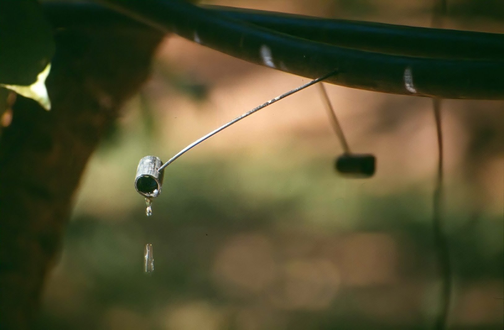
Figure 1:
Microtube emitter - Drip irrigation in an orchard, Australia 1984. [Source: © Stein, 1984]
Author / Reference
- Stein, T.-M., 2026:
The Microtube Emitter – An Early “Dripper” Widely Used in the Early Development of Drip Irrigation. -
VL Irrigation & Hydrology, Sakia.org.
VL Irrigation & Hydrology - vl_ref_id_x_0020
Introduction
The microtube emitter was the forerunner of all distributors [Vermeiren and Jobling, 1984] . It was also known as the “spaghetti tube” and was a simple, inexpensive emitter widely used in Australia during the early development of drip irrigation.
History
The microtube emitter was first used in Australia around 1960 on a small trial plot in Victoria. The development of drip irrigation was still at an experimental stage, and it was not until 1969 that the system was ready for use under field conditions.
Despite the increasing push by manufacturers towards the use of more sophisticated drippers, the microtube remained popular for many years. In 1977, the microtube still accounted for 50% of all emitters used in NSW. In Victoria, it even had a share of approximately 80%, and nearly 100% in Western Australia [Barth, 1983/84] . Over time, more advanced, less labour-intensive, and more robust systems, which were less susceptible to mechanical damage, gradually replaced the microtube dripper.
Design
The microtube is a small-bore black polythene tube of approximately 0.5 to 1.5 mm internal diameter, which is fixed to the lateral alongside the crop. To prevent water from jetting out of the tube and to create the desired dripping action, as well as to allow it to be fixed in a position close to the crop, it is inserted into a larger piece of tubing attached to the end of the microtube. In most cases, a short piece of tubing approximately 10 to 20 cm in length and of wider diameter is used, allowing the microtube to be positioned on the ground. In some cases, shorter pieces were used simply to disperse the water jet, thereby creating a dripping emitter, as shown in Figure 1.
The discharge depends mainly on the pressure, the internal diameter, and the length of the tube, and commonly lies within the range of 0.5 to 12 L/h. It may also vary according to temperature and can increase by approximately 25% for a temperature change from 20°C to 50°C in a 0.5 mm tube. This effect is less pronounced in larger diameter tubes, increasing by only 11% for a 1.0 mm tube.
In order to achieve a uniform discharge of water from the microtube outlets along the lateral, the lengths of the microtubes need to be adjusted to compensate for pressure variations along the line. Water pressure changes along the lateral due to friction losses, reductions in flow caused by discharge points, and changes in terrain elevation.
An example of discharge uniformity from microtube emitters of different lengths along the lateral is given in Table 1 . These calculations show that, over a length of 99 metres, the pressure drops from 10 m of water head at the inlet to 3.7 m at the end of the lateral. In order to maintain the design discharge rate per microtube outlet of between 7 and 8 L/h, the lengths of the microtubes would need to decrease along the lateral from 41.8 cm at the inlet to 13.0 cm at the end.
Installation and Usage
When it comes to installation, microtubes need to be cut accurately to the designed length. As suggested by Vermeiren and Jobling (1984), cutting accuracy should be within ±10 mm. The cut should be clean and made at an angle of approximately 45°, preventing the microtube inlet from butting against the lateral wall when inserted, thereby avoiding blockage or a reduction in flow.
If the microtube is inserted correctly into a cleanly punched hole created using a tapered punch, there is little danger of leakage or blowouts. Depending on requirements (distance to the plant, maintenance requirements, etc.), microtubes can be inserted only through the wall of the lateral, leaving a longer section projecting outside, or pushed further into the lateral so that only a short section remains visible.
One of the disadvantages of microtube emitters is that longer microtubes can easily be disturbed or damaged if not secured properly, or if caught by machinery during maintenance operations. This can partly be overcome by inserting the microtube further into the lateral and leaving only a short section protruding from it.
Microtube emitters are particularly suitable for undulating and hilly conditions, where pressure in the laterals varies considerably due to differences in elevation. They are more suitable for vineyards and orchards where movement of laterals is not required. Despite their simplicity, they are labour-intensive systems and are vulnerable to mechanical damage. With properly designed tube dimensions and layout, a very uniform discharge rate can be achieved along the lateral. Nevertheless, good-quality materials and careful installation are required to achieve satisfactory results, and some farmers reported difficulties in obtaining the desired discharge rate. Damage caused by rodents was also reported, and some birds apparently found these microtubes particularly suitable for nest building.
One development that attempted to overcome the cumbersome handling and bulkiness of conventional microtubes was the pre-coiled microtube. It consisted of prefabricated, stiffer polypropylene microtube coils that could be fitted neatly around the lateral. Their discharge characteristics were identical to those of straight microtubes of the same internal diameter and length.
Table 1:
Example of discharge uniformity from microtube emitters along the lateral.
Conditions: Pressure at the upstream end of the lateral: 10.0 m water head. Pressure at the closed end of the lateral: 3.7 m water head. Water temperature: 15°C.
[Source: Vermeiren and Jobling, 1984 ]
| Distance of microtube from inlet [m] |
Length of microtube [cm] |
Discharge of microtube [l/h] |
│ │ │ │ |
Distance of microtube from inlet [m] |
Length of microtube [cm] |
Discharge of microtube [l/h] |
| 1.50 | 41.80 | 7.69 | │ | 52.50 | 17.30 | 7.59 |
| 3.00 | 40.00 | 7.66 | │ | 54.00 | 17.10 | 7.35 |
| 4.50 | 38.50 | 7.69 | │ | 55.50 | 16.80 | 7.35 |
| 6.00 | 37.00 | 7.69 | │ | 57.00 | 16.60 | 7.35 |
| 7.50 | 35.60 | 7.79 | │ | 58.50 | 16.40 | 7.50 |
| 9.00 | 34.30 | 7.89 | │ | 60.00 | 16.20 | 7.42 |
| 10.50 | 32.00 | 7.83 | │ | 63.00 | 15.80 | 7.42 |
| 13.50 | 30.90 | 8.00 | │ | 64.50 | 15.60 | 7.42 |
| 15.00 | 29.90 | 7.86 | │ | 66.00 | 15.50 | 7.26 |
| 16.50 | 29.00 | 7.83 | │ | 67.50 | 15.30 | 7.29 |
| 18.00 | 28.10 | 7.66 | │ | 69.00 | 15.20 | 7.38 |
| 19.50 | 27.30 | 8.06 | │ | 70.50 | 15.00 | 7.29 |
| 21.00 | 26.60 | 7.79 | │ | 72.00 | 14.80 | 7.35 |
| 22.50 | 25.90 | 7.66 | │ | 73.50 | 14.70 | 7.29 |
| 24.00 | 25.20 | 7.89 | │ | 75.00 | 14.60 | 7.17 |
| 25.50 | 24.50 | 7.66 | │ | 76.50 | 14.40 | 7.14 |
| 27.00 | 23.90 | 7.89 | │ | 78.00 | 14.30 | 7.11 |
| 28.50 | 23.20 | 7.63 | │ | 79.50 | 14.20 | 7.11 |
| 30.00 | 22.70 | 7.66 | │ | 81.00 | 14.10 | 7.14 |
| 31.50 | 22.30 | 7.53 | │ | 82.50 | 14.00 | 7.42 |
| 33.00 | 21.80 | 7.79 | │ | 84.00 | 13.90 | 7.35 |
| 34.50 | 21.30 | 7.59 | │ | 85.50 | 13.80 | 7.26 |
| 36.00 | 20.90 | 7.66 | │ | 87.00 | 13.70 | 7.14 |
| 37.50 | 20.40 | 7.49 | │ | 88.50 | 13.60 | 7.50 |
| 39.00 | 20.10 | 7.50 | │ | 90.00 | 13.50 | 7.50 |
| 40.50 | 19.70 | 7.47 | │ | 91.50 | 13.40 | 7.45 |
| 42.00 | 19.40 | 7.53 | │ | 93.00 | 13.30 | 7.14 |
| 43.50 | 19.00 | 7.47 | │ | 94.50 | 13.20 | 7.50 |
| 45.00 | 18.70 | 7.45 | │ | 96.00 | 13.20 | 7.47 |
| 46.50 | 18.40 | 7.42 | │ | 97.50 | 13.10 | 7.31 |
| 48.00 | 18.10 | 7.53 | │ | 99.00 | 13.00 | 7.38 |
| 49.50 | 17.80 | 7.31 | │ | |||
| 51.00 | 17.70 | 7.53 | │ | |||
Reference
- Barth, S., 1984/85:
Entwicklungsstand der Tropfbewässerung in Australien. – Der Tropenlandwirt, Beiheft Nr. 20, Verband der Tropenlandwirte aus Witzenhausen e.V., Witzenhausen. - Stein, T.-M., 2003:
The microtube emitter - an early ‘dripper’ widely used in the beginning of drip irrigation. -
VL Irrigation & Hydrology, Sakia.org. - Vermeiren, L. and Jobling, G.A., 1984:
Localized Irrigation. –
FAO Irrigation and Drainage Paper No. 36, Food and Agriculture Organization of the United Nations, Rome.